
What is Power Cable?
A power cable consists of different layers of insulation sandwiched between a High Voltage conductor and a metallic sheath which as the ground of the power cable. The purpose of these insulation screens is to control electric field stress due to High Voltage applied on the conductor. Any defect to these layers will decrease the dielectric strength of these layers and can result in insulation failure of the power cable. Due to reduced dielectric strength partial discharges can happen in insulation that can keep on continuing before actual insulation breakdown.

Basic Structure of Power Cable
Why there are Partial Discharges in power cables?
A partial discharge is a localized electrical discharge that only partially bridges the insulation between conductors, and which can or cannot occur adjacent to a conductor
Consider below cross section of power cable. In absence of any defect it electrical representation is equivalent to an ideal capacitor between High Voltage conductor and metallic sheath.
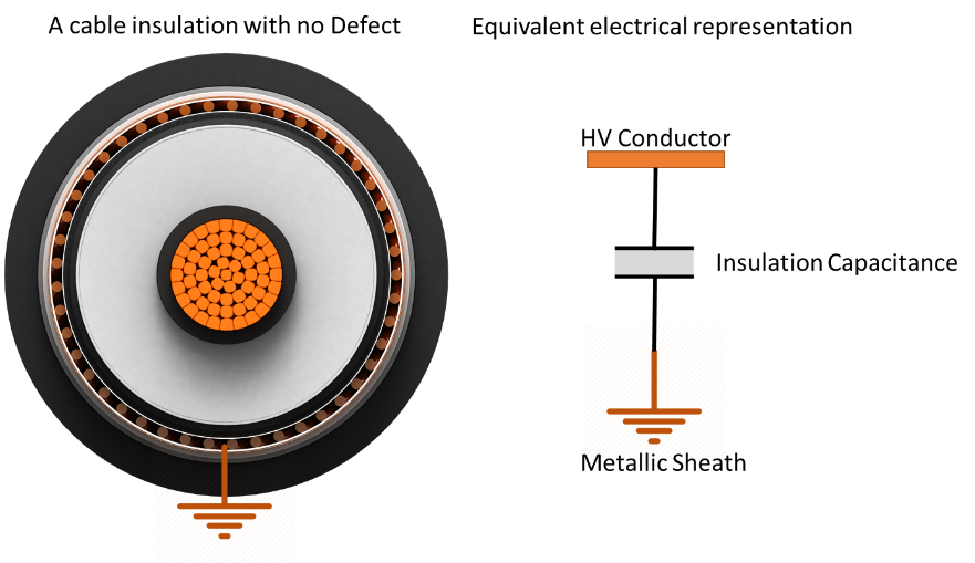
Electrical Representation of Power Cable Insulation in Absence of Defect
However, in presence of a defect, e.g., a cavity in insulation, the equivalent electrical representation of power cable will change. Due to series capacitance of cavity, overall capacitance and hence dielectric strength of power cable insulation will decrease.
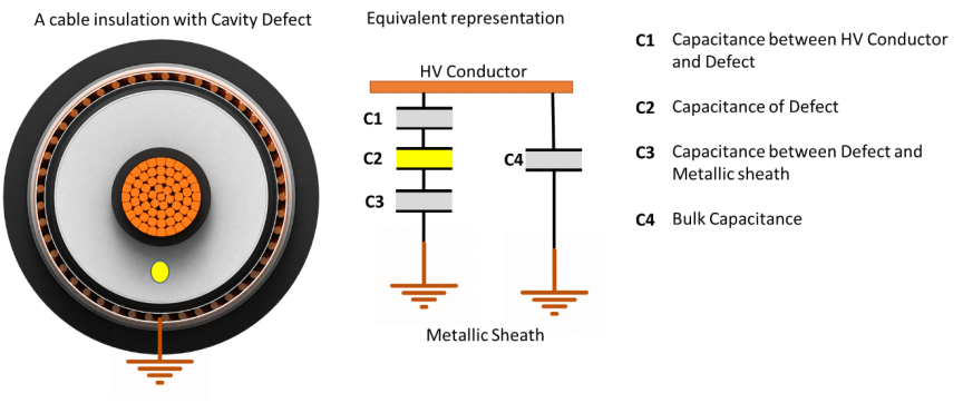
Electrical Representation of Power Cable Insulation in Presence of Defect
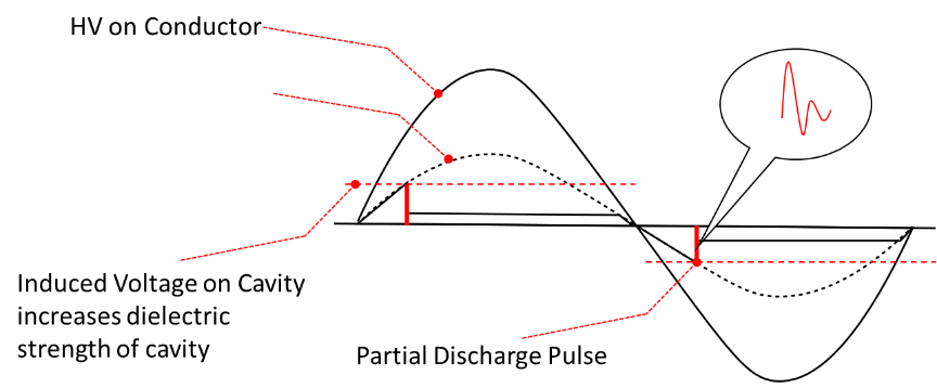
Due to decreased dielectric strength, when induced voltage on cavity surpasses its dielectric strength, it collapses resulting release of different forms of energies. This release of energy is equivalent to Partial Discharge phenomenon. One of the energies is release of High Frequency Pulses which travel along the length of power cables on both conductor and metallic sheath. Both fields on conductor and metallic sheath are equal in magnitude and opposite in polarity. Experts detect high-frequency pulses by clamping High-Frequency Current Transformers (HFCTs) around the cable’s metallic sheath, usually at the ends or terminations of power cables.
Real Reason Behind Partial Discharge Phenomenon
Guidelines to perform Online Partial Discharge Measurement?
Online Partial Discharge measurement involves monitoring partial discharge in power cables while they are energized under normal operating conditions. For the purpose of test, a temporary de-energization might be required where safe access to power cable metallic sheath is not available. Below are some general guidelines to perform online partial discharge testing.
1. Installation of High Frequency Current Transformer sensors
High Frequency Current Transformer (HFCT) are clamp on inductive sensors that can be clamped around power cable metallic sheath that is connected to substation earth. While installing HFCT sensors, the polarity of these sensors should be pointing towards earth direction. This will later help in analysing partial discharge signals and their direction. A positive pulse travelling in the direction of polarity of High Frequency Current Transformer will give output as positive pulse and vice versa.
The High-Frequency Current Transformer (HFCT) sensor must be clamped around the metallic sheath that exits the power cable, passes through the HFCT, and terminates at the earth connection. It is very important for online partial discharge measurement as mistakes do happen. Avoid such mistakes.
Three HFCTs are clamped on each cable ground to identify whether partial discharge comes from outside the cable or from one of its phases.
Experts can connect a Transient Earth Voltage (TEV) sensor inside or outside medium-voltage air-insulated metal-clad switchgear to detect local termination defects. Application of HFCT together with TEV can help identify internal versus local PD at termination
Do you know Rugged Monitoring Hsens-H (HFCT Sensor) and Hsens-T (TEV sensor) are equipped with transient overvoltage protection within sensors to minimize transients that can damage the electronics connected to them.

Application of Hsens-H (one phase is shown) and Hsens-T
2. Solving the challenge of High noise during online partial discharge measurement
Online partial discharge measurements are more challenging than offline ones due to high noise levels. Noise can be present in power supply which is powering up equipment. It can be power cable system noise or can be coming from environment. Noise can vary from site to site.
A PD measurement device must include different sets of filters, as no two sites are ever the same. There are different techniques available in commercial systems that can help in eliminating or minimizing noise on site.
Did you know that Rugged Monitoring’s HPM601 Partial Discharge Monitor uses real-time band-pass filters? These filters are software configurable with different options of bandwidths and cut-off frequencies. In addition to Band-Pass filters, the HPM601 Monitor applies Wavelet and Moving Average filters in real time to the acquired data. These collection of multiple options of filters make on-site experience like a breeze.
3. Select the right partial discharge monitor to analyse multiple signals
When doing online partial discharge measurements, there can be multiple signals, multiple PD sources or multiple noise signals. Using its string denoising features, the HPM601 PD Monitor from Rugged Monitoring eliminates most noise signals.
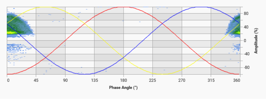
Phase Resolved Partial Discharge Graphs also known as PRPD graphs are one the best tools to identify type of defect. Different types of defects have different patterns of PRPD. Hence a knowledge of these patterns will help in better analyzing PD activity.
PRPD Graph of Corona Discharge

PRPD Graph of Surface Discharge

PRPD Graph of Internal Discharge
HPM601 transfers recorded data using its gigabit ethernet with transfer speed of 10,000 waveforms in high resolution mode. This is also 100,000 peak values of waveforms in low resolution mode. This enables the user to visualize good quality PRPD graphs and help in identifying defect type.
4. Make sure to perform partial discharge measurement during soak test
It is common procedure to perform a 24-hour or 48-hour soak test on newly installed or repaired power cable. The test energizes the cable for 24 hours without applying any load.
In most of these soak tests by cable installation companies or cable owners, a major element is missing. This is PD measurement during initial 24 hours or 48 hours of soak test. These soak tests on power cables do not include partial discharge (PD) measurements. Perform partial discharge testing during the entire soak test. This is to ensure that power cable and its accessories are partial discharge free.
HPM601 Rugged Partial Discharge Monitor
The HPM601 PD Monitor includes up to 1 TB of industrial SSD drive. This enables the user of system to leave monitor on-site without laptop. Monitor will keep on recording data for 24 or 48 hours continuously. The monitor stores data in its internal memory, allowing users to download it later to a laptop. This will ensure to record any PD activity which might be present during soak test.